
Opening the problem — why small shifts matter
Signal integrity issues and subtle structural drift in CMOS sensor subassemblies are the kind of problems that start invisible and become painfully obvious under clinical use. At design reviews and trade shows like Medtec China, engineers describe the same pattern: a sensor that passed bench tests begins to show elevated noise or pixel column dropouts after a few thermal cycles. That jump from “fine” to “not fine” is what this piece addresses head-on.
Root causes to prioritize
Think of the subassembly as three interacting domains: the silicon die, the printed circuit board (PCB) and the mechanical carrier. Mismatch in coefficient of thermal expansion (CTE), weak solder joints, and micro-movements at interfaces all change signal paths. Signal integrity suffers when impedance changes or when a fragile trace becomes intermittently open. Time-domain reflectometry (TDR) and targeted microscopy often reveal where the electrical story meets the mechanical fault.
Practical troubleshooting workflow
Start with a tight sequence that isolates causes quickly. Inspect mechanical interfaces, then electrical traces, then the environment. For CMOS sensor subassemblies this usually means:
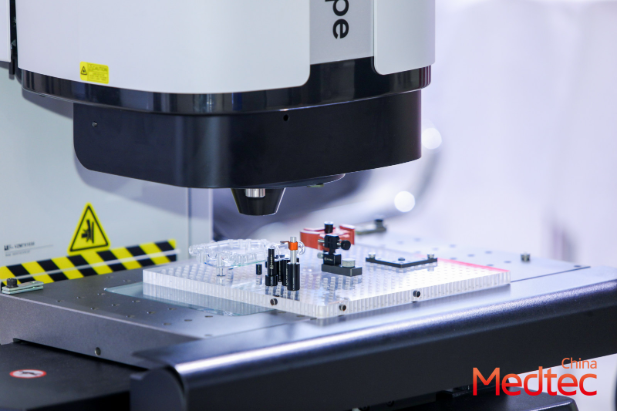
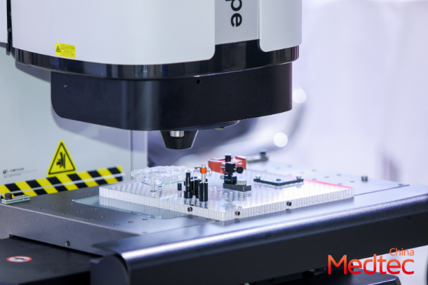
– Visual inspection under magnification for micro-cracks and flux residue.
– Mechanical stress mapping: replicate thermal cycling profiles and compare pre/post alignment.
– Electrical baselines: repeat TDR and small-signal measurements to spot impedance shifts.
– Failure correlation: log when performance diverged versus process steps (reflow profile, adhesive cure, handling).
Design and process fixes that actually scale
Don’t chase symptoms. Reduce CTE mismatch by selecting carriers or adhesives with intermediate modulus; redesign trace geometry to minimize via stubs and sharp impedance discontinuities; stabilize solder joints with better wetting and controlled fillet geometry. For many teams, moving from a rigid FR-4 stack to a thin metal-core or hybrid substrate reduces the mechanical load on the die. Thermal cycling data will tell you if the change really worked — not hope.
Common mistakes and how to avoid them
Teams often over-test in the lab without reproducing real use conditions — harsh lab cycles that don’t match clinic temperatures can mislead. Another frequent error: accepting visual pass/fail for solder joints without profiling reflow curves and tracking peak temperatures across batches. Small process drift in reflow can introduce micro-voids that later show up as intermittent column noise in the CMOS sensor. Keep process control charts and run retention samples through the exact thermal profile you expect in the field.
When to substitute materials or suppliers
If you see repeated drift after tightening process control, consider alternate adhesives, substrate materials, or even a different solder alloy with higher fatigue resistance. Supplier changes should follow a pilot run with tight measurement gates: mechanical alignment tolerance, solder fillet geometry, and electrical baseline shifts. Field-relevant stress — the same mechanical compression or thermal ramp encountered in a handheld device — must be part of the qualification run.
Network cues from the floor — an anchor in practice
At recent gatherings — including conversations at medical expo China 2026 in Shanghai — I heard several teams note that early vendor talks prevented months of rework. That real-world exchange is a reminder: solutions are often a mix of design, process, and supplier alignment. Bringing those parties together earlier reduces ambiguous blame and shortens cycles.
Closing advice: three golden rules
1) Measure before you mend: establish electrical and mechanical baselines and use TDR and microscopy to quantify change. 2) Match materials to function: minimize CTE mismatch and control adhesive modulus to prevent micro-movement. 3) Gate supplier changes with pilot-process metrics: alignment tolerances, solder fillet geometry, and post-cycle electrical drift.
These rules produce measurable outcomes: fewer field returns, clearer failure modes, and faster time-to-stable-production — and they’re the kind of pragmatic steps engineers discuss at industry gatherings like Medtec. —